|
05/01/01 Doesn't seem like a month since collection day.. First job today, fitted the tunnel top. No problems here just followed the video. There was about 14" or so left off from the large end of the tunnel top which it turned out I need to make up the shortfall in the section for the front tunnel top. (the one you cut out of the floor to fit the gearbox/engine). It looks a bit like one of grandmothers patchwork quilts, but the carpet will hid this and I am sure several other messy bits.
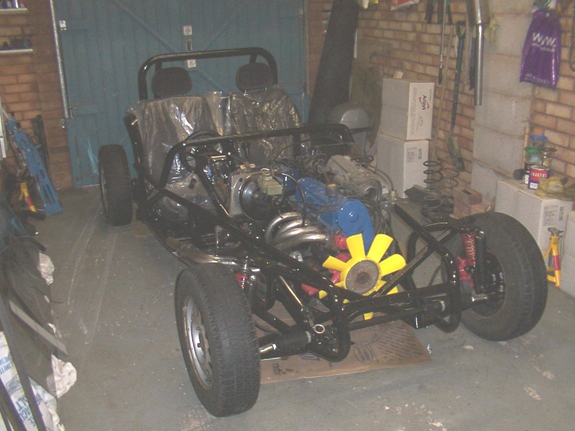
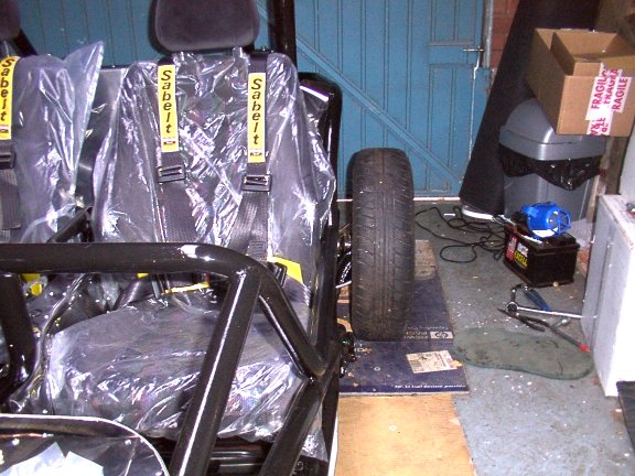
A mate came round and bought all 5 of my alloy wheels and tyres, (195x65x14), and left me with the wheels off his ford van until I have tyres for my RHE alloys. Looks a bit different with the 165's from the van and bags of clearance, around the sliding pillar/spring. I will wait until I have fitted the alloys before ordering spacers as I am not sure how the offset of the RHE alloys affects the clearance.
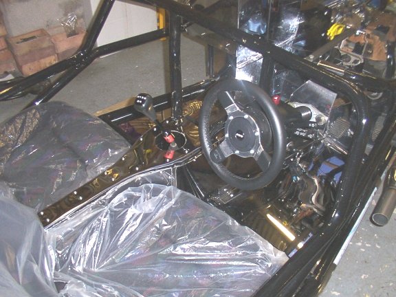
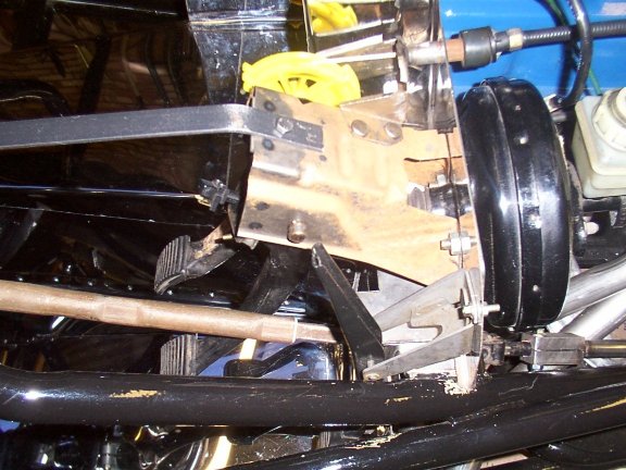
Started trial fitting the pedal box in order to fit the firewall panels. Talk about the Krypton factor !, there are a lot of variables to take into account when fitting the pedal box, ie clearance of pedals to tunnel side, clearance of pedals to footwell end, clearance of pedals to steering shaft, position of steering bush bracket. You constantly need to adjust then get in the car, try everything for size, get out adjust , get in etc… I finally decided on a suitable position and clamped the servo plate into position. I then used the offside fire wall panel fitted to the servo plate as a guide for the remaining fire wall panels. This is where I made a cockup because the nearside panel ended up just over an 1" to far over, the little 'v' was offcentre and more importantly the battery tray now ended up 1" to narrow and the battery wouldn't fit !. At this point I packed up for the day and went off to B&Q, picked up some more self tappers and some mastic tape which will supplement the silicon sealer for filling large gaps. The tape is on a 2" roll and cuts nicely into smaller strips, it's self-adhesive and moulds well.
06/01/01 Having clamped up the servo plate I now bit the bullet and bolted the plate into place. I noticed that because the steering bush bracket is under the servo plate, spacers are need under the other edge of the servo plate so that it tightens up nice and square. Fitted the steering bush kit and cut the steering join from the sierra shaft to make up the difference between the end of the steering wheel shaft and the RHE shaft. I had the same problem other people have had in that the 'pinch' bolt on the RHE shaft would not tighten up on the sierra shaft, so I fitted copper shims, (15mm central heating pipe), inside the pinch bolt, now it tightens up fine. The shaft fouled on the 4 into 1 manifold, after adjusting the steering column as much as possible the solution was to rotate the steering rack upwards slightly, this gave me about 10mm clearance past the manifold.
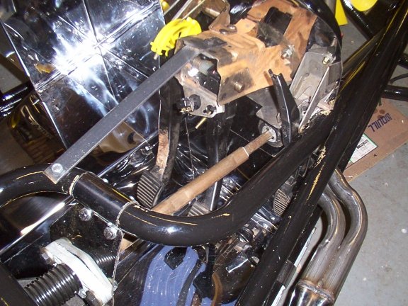
Fitted the pedal box next no real problems except that the accelerator pedal looks like it will need a spacer to bring it in line with the other pedals, (can't remember it being offset forward on the sierra). Fitted the clutch cable and servo/master cylinder. As expected the pedals are a bit on the high side for my dinky size 8 feet, I will have a raised floor in this area. The seat / pedal arrangement seems okay although I would have thought that with the steering wheel nearly in your lap, it must be a bit difficult for 'larger' people to get in and out.
Now I decided to fix my cockup with the fire wall panels. This time I made sure the little 'v' was in the centre of the car then cut/bent and formed the other panels to suit. All fits now except that the battery tray now has 1" missing from the nearside. Pop riveted in an offcut to make up the difference and the battery now fits. About time I had some working brakes, so I ordered 25ft of brake pipe to supplement the meagre amount included in the kit. I also borrowed a brake pipe flaring tool to make my new 'ends'. Before fitting the hydraulic brakes I fitted the handbrake. This is mounted on top of the tunnel between the seats, unlike the video which suggests fitting on the floor beside the passenger side of the tunnel. A length of 1 ½" angle was then fitted to the top of the rear chassis tubes just behind the back panel. The angle was slotted to allow for the handbrake cable adjusting mechanism, and bolted to the chassis. Next I shortened the handbrake cable and fitted a new nipple by drilling an 8mm bolt , sliding onto the cable and hitting with a large lump hammer, seemed to do the job fine. Fitting new brake shoes and the handbrake cable was a bit of a pain, getting all the springs etc all assembled and not loosing any fingers in the processes. Once the wheels were back on, the cable adjusted nicely to give a firm handbrake. The 3 way union for the rear brake pipes was also mounted on the same piece of angle.
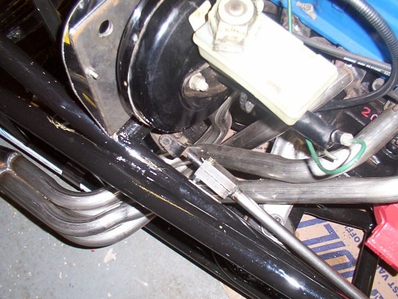
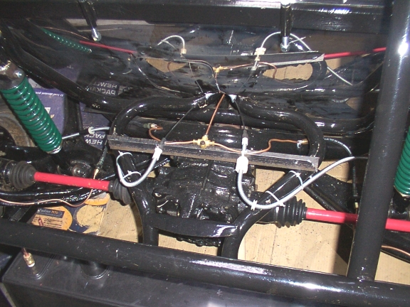
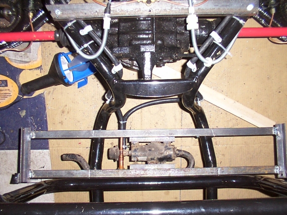
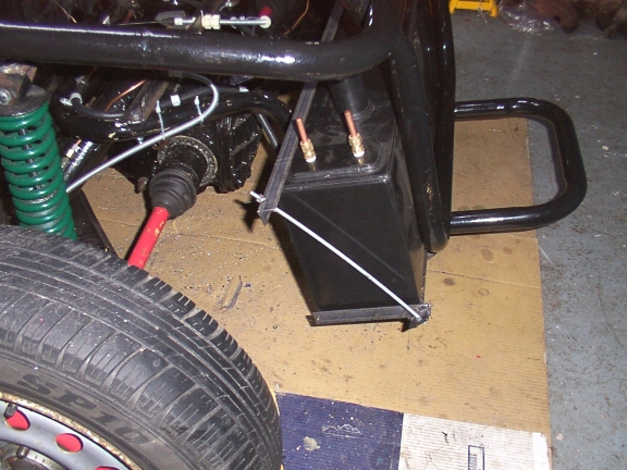
Now time to make up the hydraulic brake pipes.. I located the deceleration valve inside the tunnel beside the gearbox at the recommended angle of 30 degrees. I then ran the main length of pipe included in the kit, back down the tunnel to the 1" flat at the rear and fitted to the 3 way union. Next I ran a length of pipe outwards from the union at the rear to each wheel, connecting to the flexible hoses bridging the gap between the axel and wheel back plate. I used the supplied pipe first to avoid making up to many ends. The front 'little' end of the deceleration valve goes to the rear and the rear of the valve outlet goes to the rearmost, (closest to the servo), connection on the master cylinder. I now ran a length from the deceleration valve out of the front tunnel, up around the firewall and into the master cylinder. Next two lengths were run from the master cylinder to the front wheels,(by now I had used up the supplied pipe). The nearside pipe runs back across the firewall then down the inside side tubing. All pipes were 'P' clipped in place. 13/01/02 All the pipe were now fitted so time to bleed the brakes, I purchased a one man self brake bleed kit from Halfords, they lied, you need two people, one to hold the pipe in the bottle to catch the fluid, and tell you if anything is happening. It took ages to pump all the air out before any fluid started to appear, then hey presto brakes!. I re-adjusted the handbrake and stood back to admire my completed braking system. Had a look at mounting the radiator, because I am using the Injection engine with the large yellow viscous fan , there is not enough room for the radiator in the suggest position. ie on the cross member in front of the fan. A couple of 38mm exhaust clamps later and the radiator is mounted on the very front cross member in the nosecone. I will also fit an electric fan on the back to aid cooling and ensure the in-fill panels drive all air-intake through the radiator. Radiator hose shouldn't be a problem as I have seen a selection of ribbed flexible radiator hose in Halfords up to 690mm long. Long before this stage other builders have normally fitted some of the exterior panels. I am leaving the panels until after the engine has been started, mainly because it is much easier to get at everything and not worry about putting a dint in the panel. I am sure by now I would have slipped with the drill and dinted a panel or two. Next weekend I will have a go at connecting fuel pipe, filter, pump and tank. Before attempting to fit the fuel lines, I first decided to fit and mount the tank. I have purchased a plastic tank with internal baffles for the injection engine, so it was not possible to 'weld' fixings to the tank. The simplest solution was to make up a frame for the tank to sit in whilst also provide fixing points for the fuel pump. I am using the donor gravity fuel pump and needed to fit the pump under the tank as per the donor.
As you can see by the picture is was a simple matter to re-use the original mount for the fuel pump, and then just bend the fixing hole tabs flat and screw to the tank frame. (I have yet to clean and paint the frame and pump). The fuel return pipe comes back to the pump 15mm inlet. To mount the tank I got hold of some 5mm threaded rod from B&Q , then used a piece of 1" angle and clamped the whole lot up just like the fixing I have seen for some batteries.
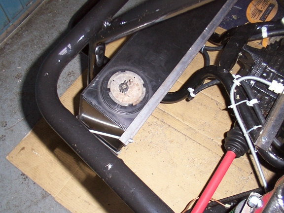
Now for the fuel lines. As I am using the injection system both my flow and return pipes need to be 8mm OD . I bought a reel of copper pipe and 4 meters of flexible for the end connections. The copper pipe I ran along the passenger side of the tunnel, both flow and return clipped with P clips. At the engine end the pipe terminate just inside the end of the tunnel, then the flexible runs to the filter, fuel rail and pressure regulator. At the other end the copper pipe terminates on top of the axle, with flexible then running down to the fuel pump. The sender unit fits nicely in the supplied thick plastic pad, all I have to do is use self tappers and pull down onto the original rubber gasket.
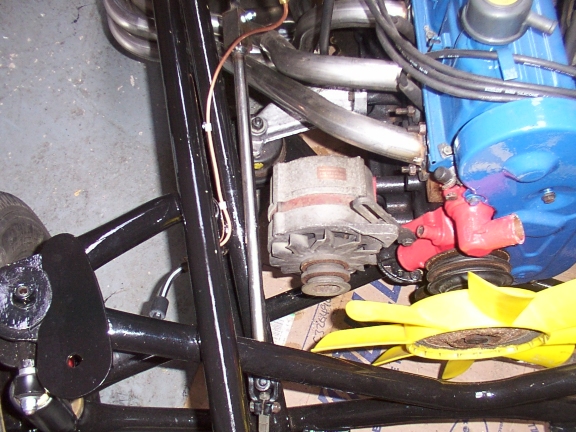
20/01/02 Fitted a few items on the engine today. The coil mounted nicely with a 'P Clamp' onto on of the supports for the EFI Plenum Chamber, the fuel filter was simply clamped to the chassis with a big jubilee clip. Next the alternator, I had read about a few problems fitting the alternator, the video tells you to turn the mounting upside down. However mine is the cast solid type so that won't work. Instead I found that if you leave everything as is it all fits but you don't have much room for belt adjustment. To give more adjustment I ground away a large section of the mounting where the top right fixing hole is, this then allows the alternator to pivot another 15mm or so. You are now only left with two fixing bolts unless you use a countersunk bolt for the fixing point. You can even still use the same steady bar and it's fixing points.
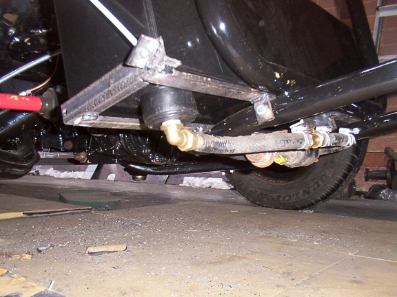
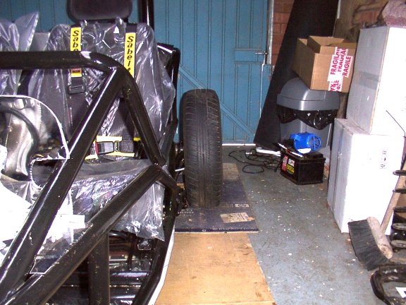
Preliminarily fitted the seat belts, mainly to work out where the inside fixing point needs to be. It looks like my best option is to weld an upright plate on the 2" angle used under the car for fixing the seat. The plate will then poke up through the floor complete with welded , ie captivated 3/8 UNF nut for the seat belt. Blast, just dropped my welding mask an broke the glass, I tried welding with one eye shut and a piece of broken welding glass over the other. Admitted defeat and stopped for the day. I am very close to starting the engine now so it looks likes like next week I will have to sort out the wiring loom, (nightmare!). Not much done this weekend, spent Saturday at the pantomime with the girls and Sunday with a hangover. I was going to have a go at the loom this weekend, but felt that in my present condition I would attempt something a bit simpler. Still I did manage to get the valve seals replaced on the engine. I borrowed a nice little compression tool from Jim Stott. This little too allows you to replace the seal without removing the cylinder head. I used a short length of 15mm copper pipe as a drift for fitting the new seals. My Pinto engine did not seems to have the classis signs of valve seal wear, ie smoking on start-up, but I thought it prudent to replace them anyway. Here's a link to Jims Instructions for replacing the valve stem seals on the rhocar site. http://www.rhocar.org.uk/buildtipz/027.shtml I also got hold of some angled wheel spacers from Jim for the rear wheels. This is basically to overcome the negative camber induced by the Sierra independent suspension. The effect is to make the car look like it is 'squatting' when viewed from the back, ie the tops of the wheels tilt in towards the body. Whilst this is not a problem, I felt it does not look aesthetically nice and reduces the tyre to body clearance at the top of the wheel. Unfortunately I had a slight problem with the spacers, (which fit between the brake back plate and the axle face), the spacer have been made with a 77mm dia for clearance over the half shaft. However on my car the 'can' on the C.V joint is 80mm, so I was unable to slide the spacers over the half shaft. I contacted Jim who said he had not come across this before, but offered to open out the ID for me. Not wanting to trouble Jim, a very nice chap at work opened out the ID for me, the spacers then went on no problem and made a marked difference to the wheel alignment. Other builders have commented this solution also seems to help handling.
With the spacers fitted I positioned my newly acquired Mini heater
and gave up for the day..
|
![]()